![]()
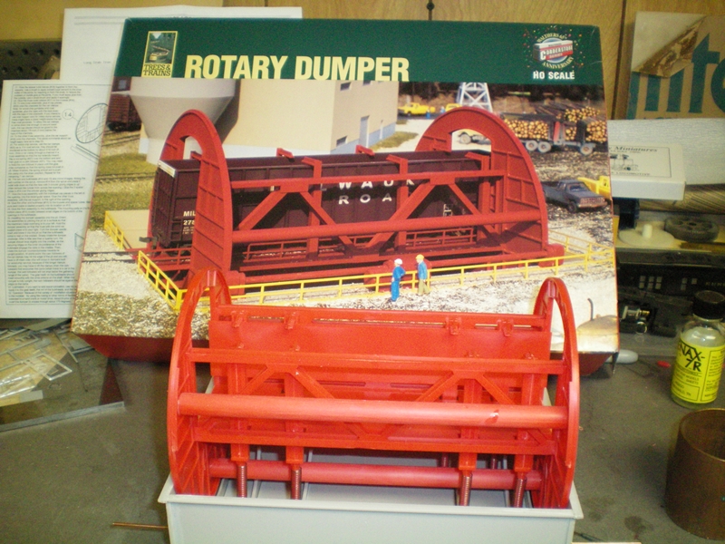
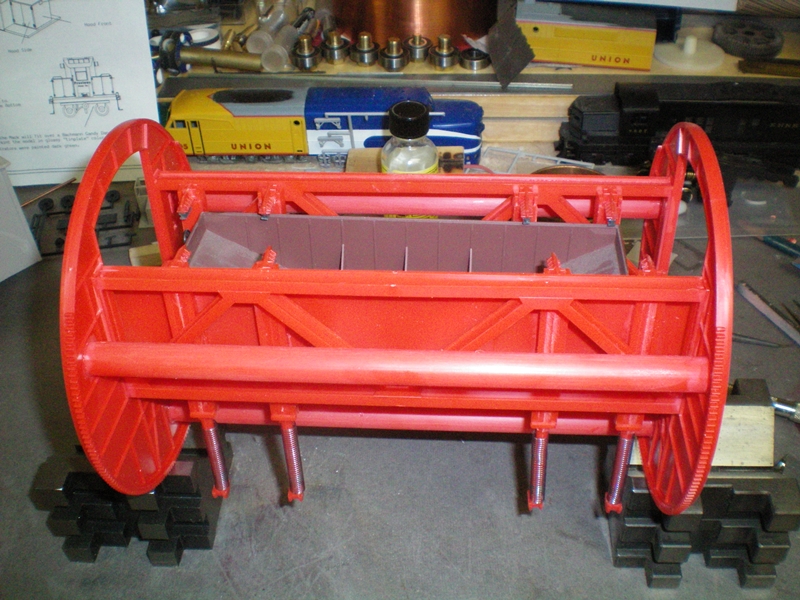
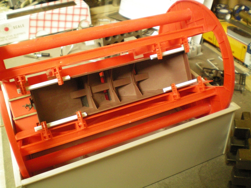
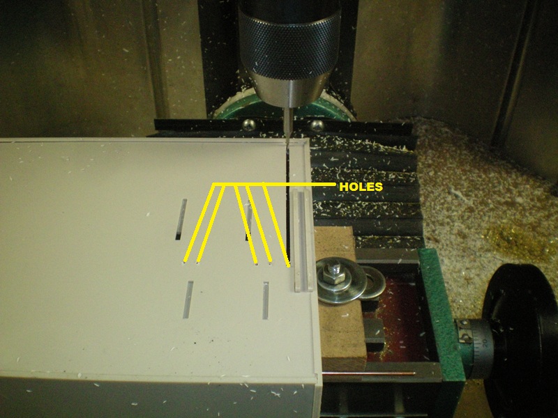
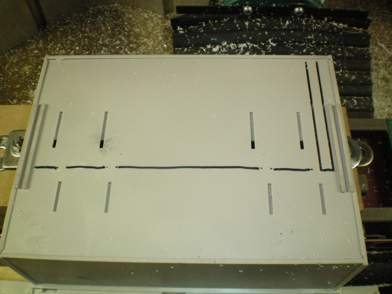
Here's the rotary dumper finished per instruction and the kit box.
 |
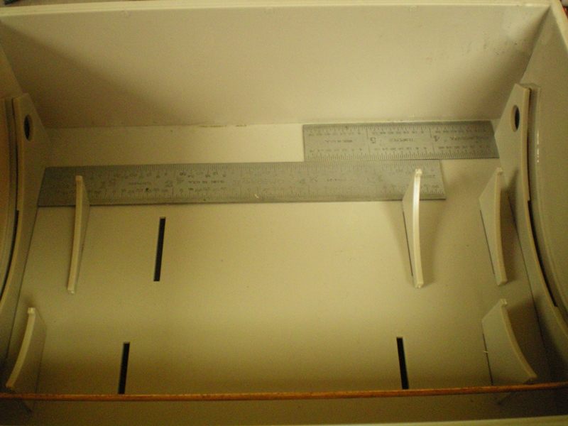
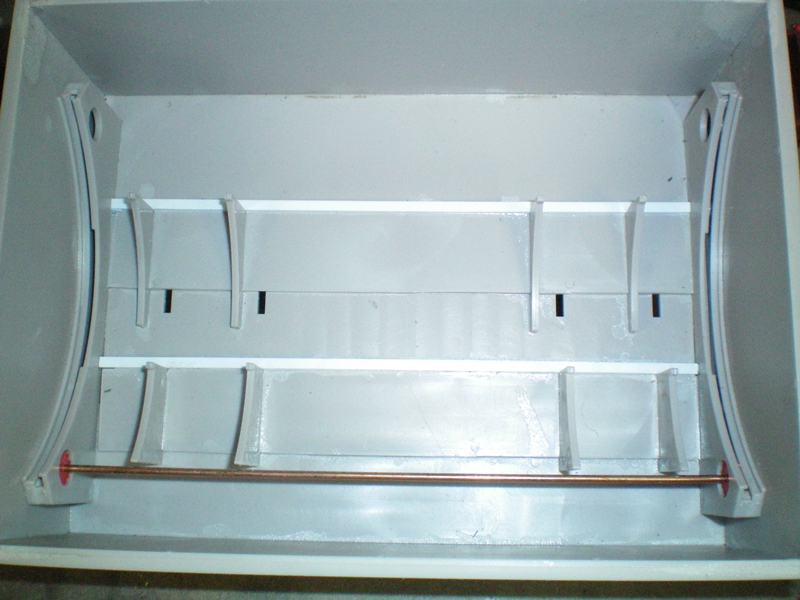
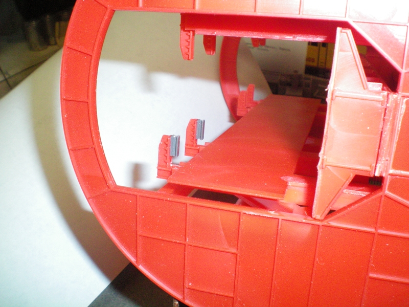
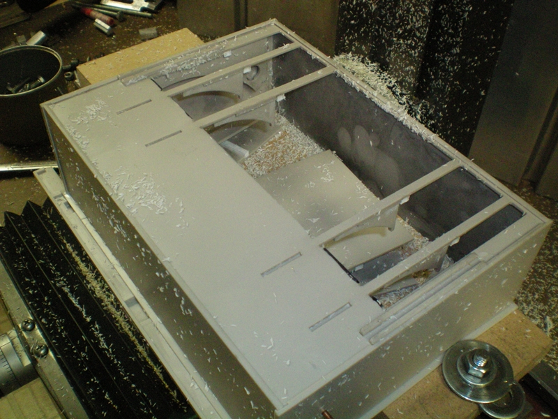
When I installed the dumper into the pit I got a surprise. The bottom part of the grippers that ride on the cams in the pit didn't line up with cams. What happened? Well when I put the floor in I didn't look at the drawing on proper orientation of the floor and I got it in backwards. Luckily I hadn't glued down the cams yet. So now I needed to come up with a fix. The next couple of pictures will show what I did to fix that plus how I modified it to work with two bay to quad standard hoppers.
 |
Here's what it looks like done wrong. The whole floor should be flipped over to make it correct.
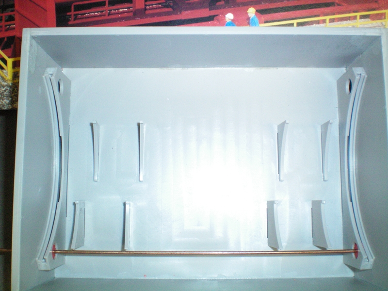 |
Here's another look at it without the cams. The shorter two slots on the left should be on the right in relation to the gear shaft.
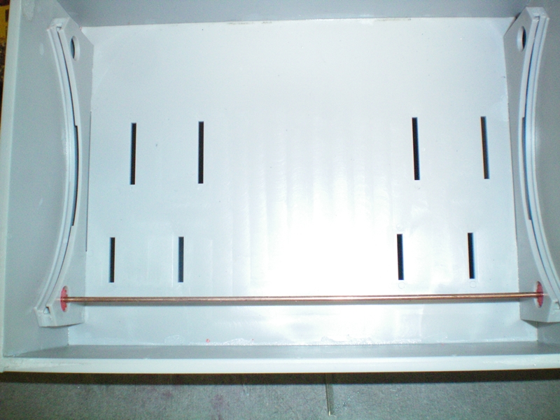 |
Here's the fix. I measured the distance between the two walls, approximately 7".
 |
Then I cut two lengths of .125" square styrene and glued them down to help align the cams.
 |
Next I measured from the edge of the slot to the wall. Then I cut a piece of styrene that distance and glued it down on the opposite wall.
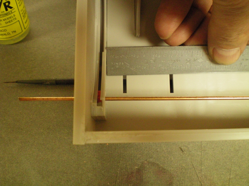 |
Here you can see the small piece of styrene, by the way I used the left over pieces that came from making the pit shorter. I'm gluing in the first cam useing a 1-2-3 block to keep it square. The bottom tab's of the cam that fits into the open slots need to be cut off and filed flat.
 |
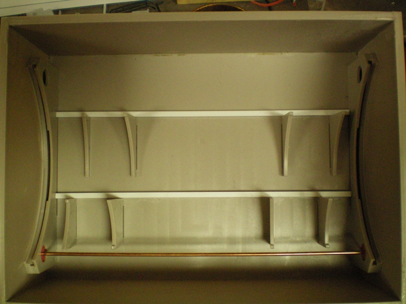
Here's the completed re-aligned cams. I made the styrene pieces the correct size to space the cams correctly. Notice the holes where the cams would have been installed as compared with were they are.
 |
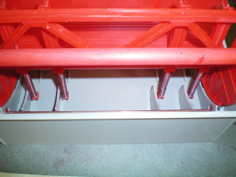
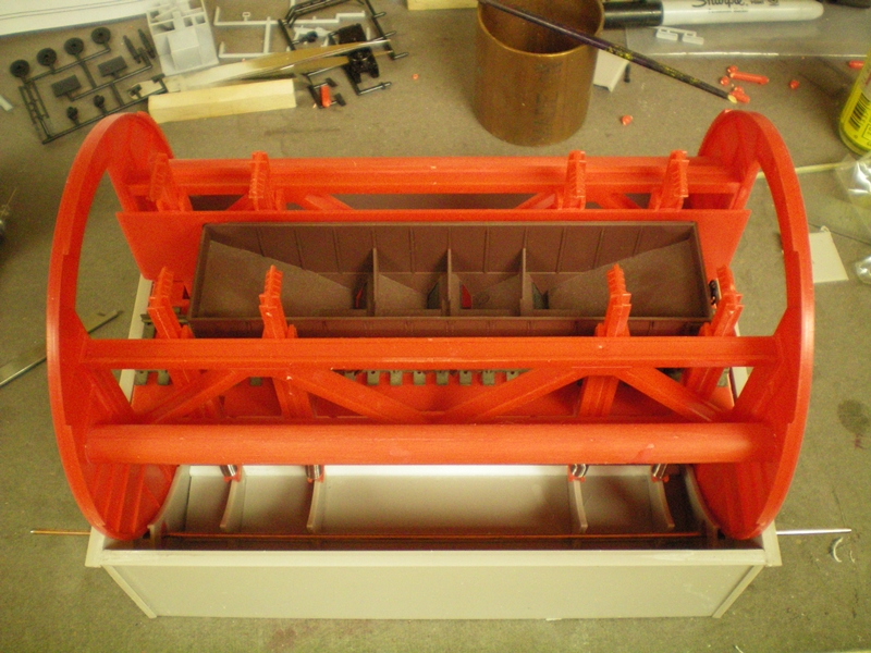
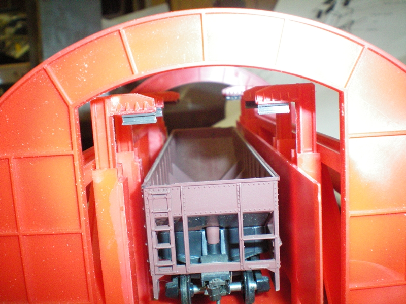
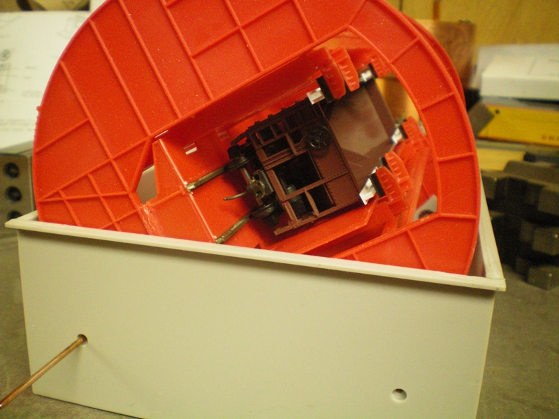
With the cams now installed correctly I wanted to see how the grippers line up. With the dumper in the load/unload car position, you can see the great distance from the top of the hopper to the opened gripper is quite large. The next step is to get the grippers down further.
 |
The first part of the solution was to glue a 1/8" "H" channel to the bottom of the gripper. Make sure it's short enough and glued right at the edge of the gripper so it won't interfere with the back part of the gripper.
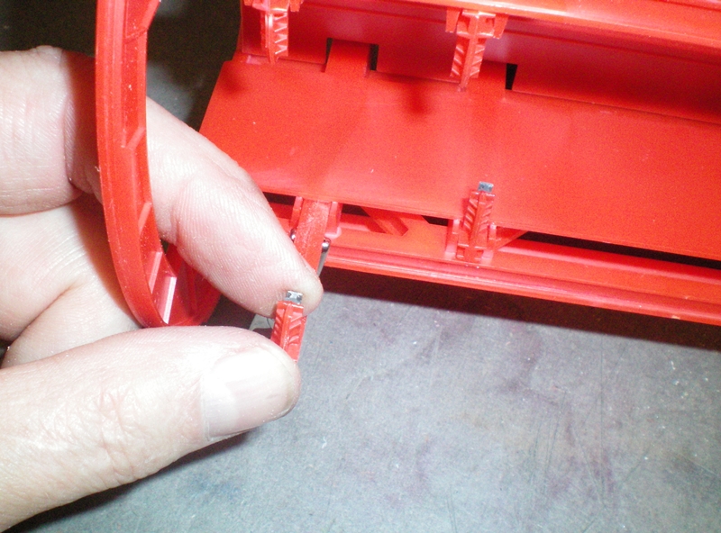 |
Here's a little item that helps hold the grippers extended to their highest position to facilitate the gluing of the small "H" channels to the bottom of the grippers. It's called an alligator clip. They can be bought at any store selling electrical products.
 |
Here's a better view of the "H" channel glued to the gripper. I made them about 5/16" long and glued them close to the front of the gripper so it will clear the back side.
 |
With the dumper in the load/unload car postion you can see how much the grippers need to come down to hold the car.
 |
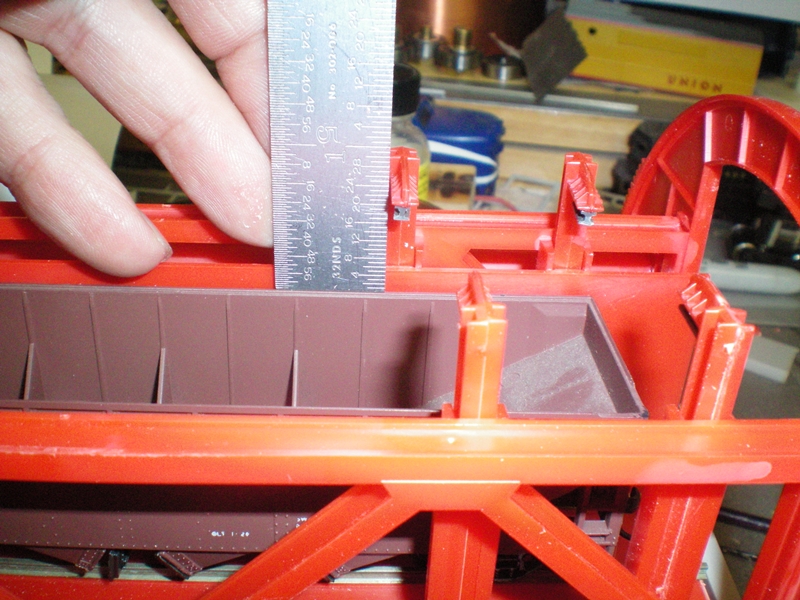
I measured the distance from the top of the hopper to the bottom of the gripper. It was about 3/4". So next I had to shorten them up.
 |
Here the rotary drum is sitting on two v-blocks. You can see that the grippers are just barely touching the top of the hopper. The solution is to cut off the cam ridders, shorten the stem and re-glue the cam rider. The next several pictures will show the procedure.
 |
I used a set of side cutters to cut off the cam riders. If you build this kit to be able to use plain hopper cars then this should be done before complete assembly of the rotary drum
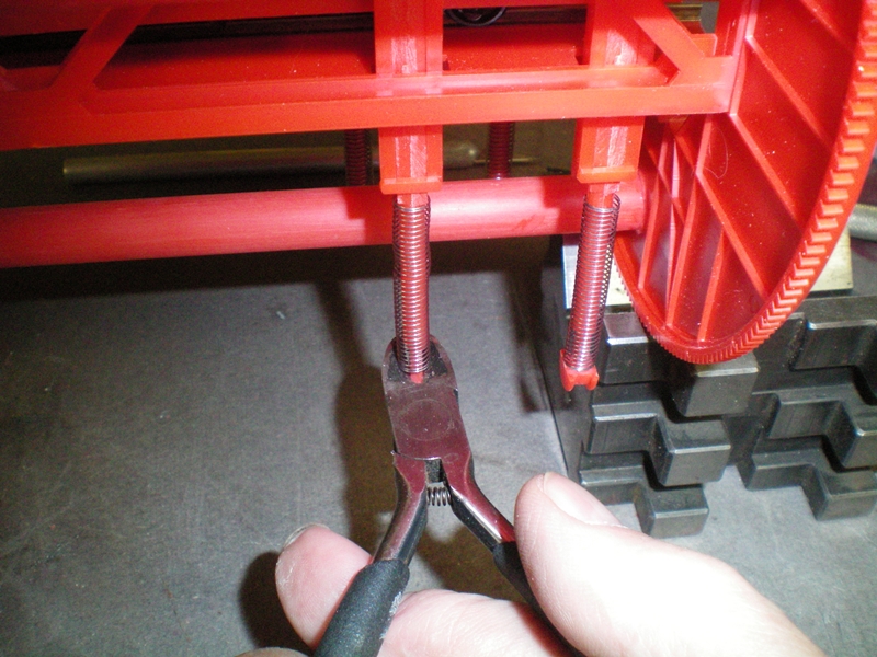 |
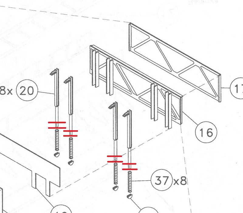
The red lines on the diagram show where to cut the bottom of the gripper shaft. File flat and file the cam rider flat then glue on the bottom.
 |
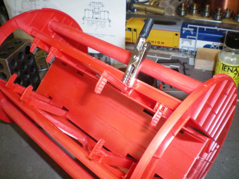
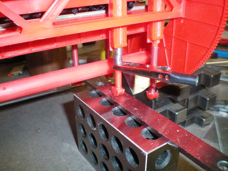
Again I used the alligator clip to hold the spring, remember to put the spring on before gluing, up while the cam follower was glued to the bottom of the gripper shaft. I use blocking to hold the cam rider up against the gripper shaft until the glued joint dried. This is the way to do all 8 gripper shafts.
 |
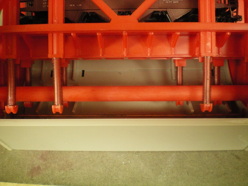
Here's a picture of the cam riders glued on to their new positions.
 |
To finish off the holding grippers I glued on an "T" beam made from a piece of .060" thick by .109" wide on a piece of 2" X 12" HO scale styrene. This was glued to the bottom of the "H" channel.
 |
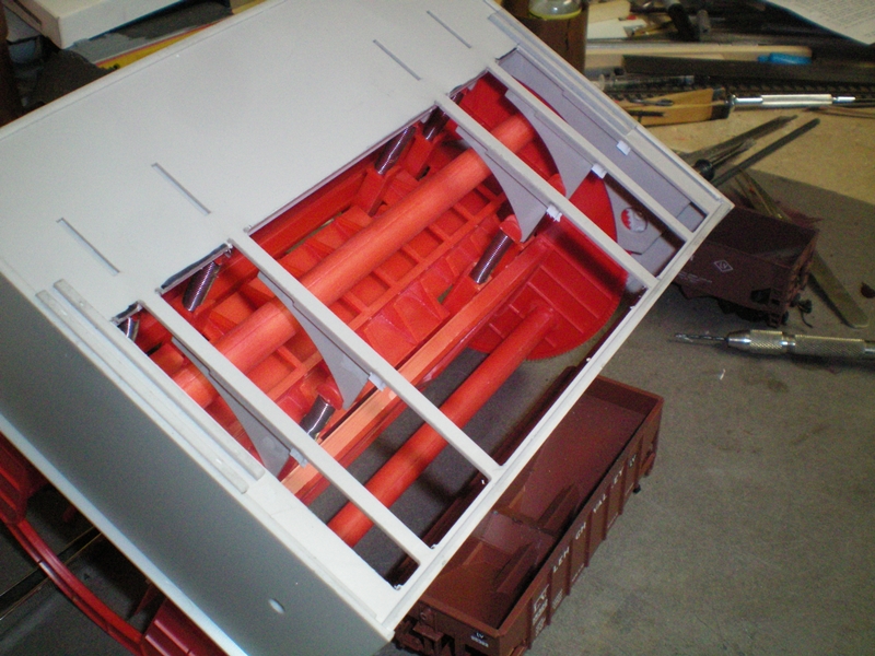
The final test. The modification seems to have worked. The gripper is holding the car on the tracks as it rotates to unload it's load. I need to test it with a load of coal, but not right now. I need to motorize the dumper first.
 |
Next will be to install a motor to turn the drum. I've got several ideas for a motor. I've got some sources of motors that probably won't disappear any time soon. And they are quite cheap.
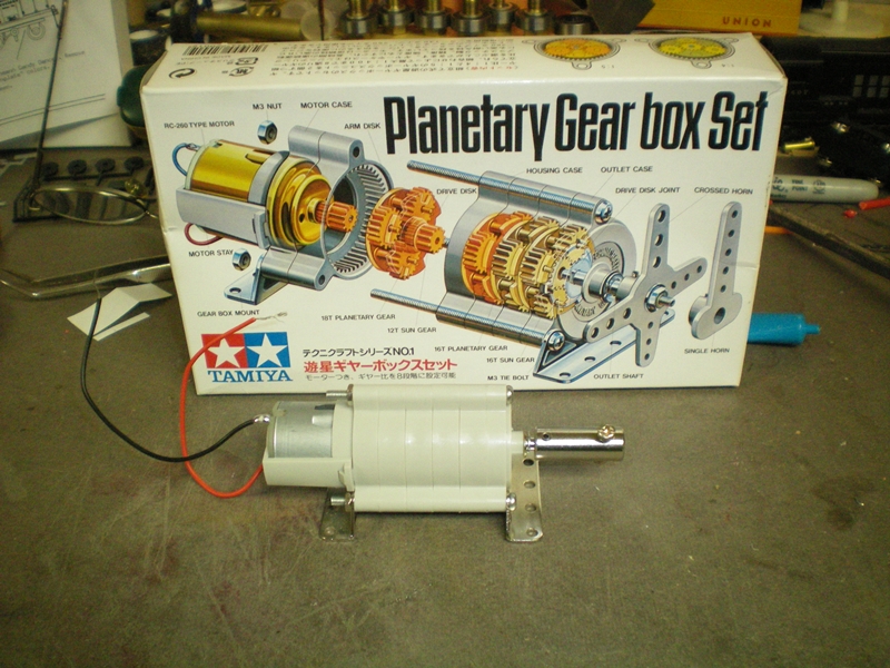
I looked through my motor collection. I had several surplus motors with gear reduction drives but decided against using one of them. It's hard enough for a modeler unfamiliar with what's available in motors out side the model railroad box. So here's a nice little motor with easy to assemble gear train from Tamiya. If ever you need a motor in the low voltage range think "robotics". Do a search and you'd be surprised at the amount of products that can be used for model railroading. Here's the site where you can purchase such an item. Pololu Robotics & Electronics This happens to be their main page. Scroll down till you see Motors and Gear Boxes. Click on that and you will see a large selection of motors. So this is what I used and it works very well.
 |
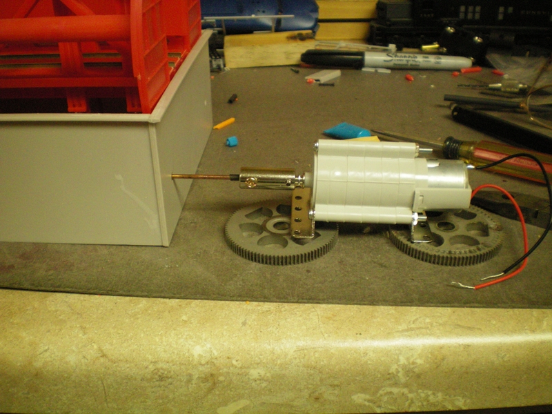
I think I've got the right motor and gear combination to do the job. This is a temporary set-up to see if this drive system will work. It's set up for a ratio of 400 to 1. The motor spins at 10,500 RPM at the 3V volt limit. That gives 10,500/400= 26.25 RPM at the output shaft. This gives a nice speed on the rotary drum. Another way to slow the drive down is to use 2 volts or 1.5 volts to drive the motor. You have to be careful using a planetary drive like this since it multiply's the torque of the motor many times. If there is any hang up in the whole drive from the rotary drum back to the motor drive you will loose a gear or two in the drive system. Remember these are plastic gears and can not take a heavy load. It'll find the weakest link and break it.
 |
Now that I've got a drive system that'll work time to make the pit operable
I had run some real coal through the hopper and found a problem that need to be remedied. I'll discuss this later. right now a workable pit needs to be designed. Next is to cut out the bottom without cutting the cams out. I first drilled holes in the bottom next to the cams to locate them when I turned the pit upside down. Then using a 1/16" cutter I cut the first slot. If you don't have a mill then you'll need to mark the holes at both ends and draw or scribe a line between the holes and then use a small saw or scraper to score a line between the two holes. Now I know where the cams are.
 |
An after thought. I marked the portion that will need to get cut out with a black marker. This way I was assured that I won't cut out a cam or two.
 |
A few minutes of cutting and the proper sections of the floor are cut out.
 |
Here's what the bottom looks like with the rotary drum installed. Notice the cam riders sitting on the cams. All four are there. I must have done it right.
 |
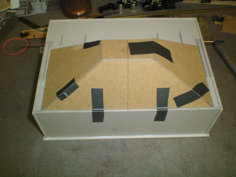
Next a hopper was mocked up using cardboard. Next will be the styrene.
 |
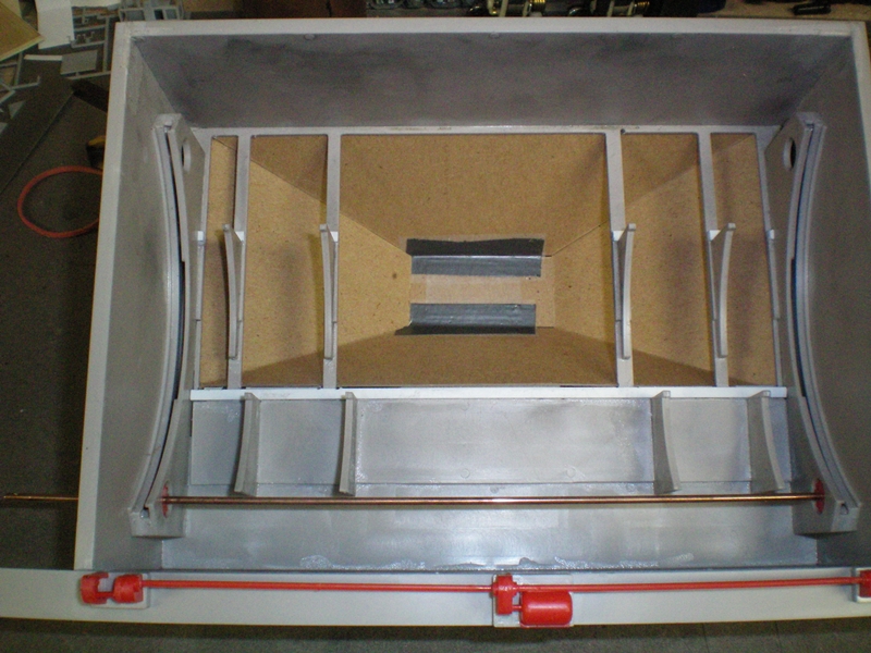
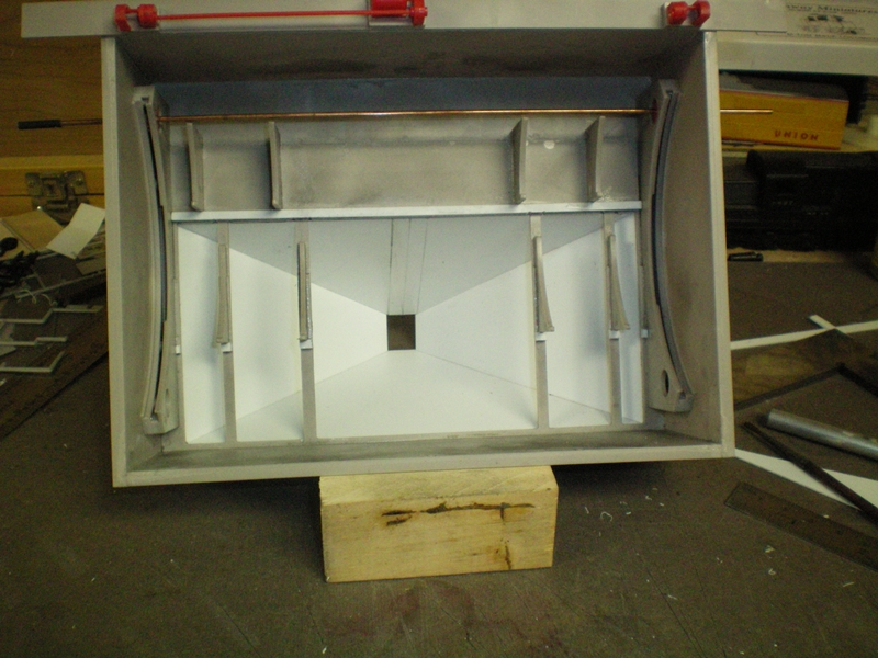
Looking in from the top, rotary drum removed.
 |
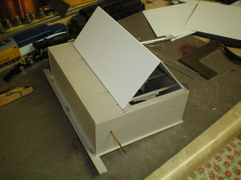
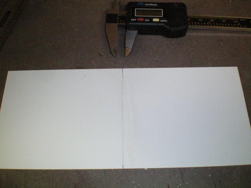
Time to make a permanent hopper from a sheet of 6" X 10" X .030" styrene. I measured between the two taps sticking through from the cam support. That size is about 6 7/8" long. I cut two pieces of .030" styrene 6 7/8" by by 3" wide. I propped them up to see what it would look like.
 |
Then I split the 6 7/8" dimension in half and drew a center line.
 |
Next I measured a ¼" on both sides of the center line.
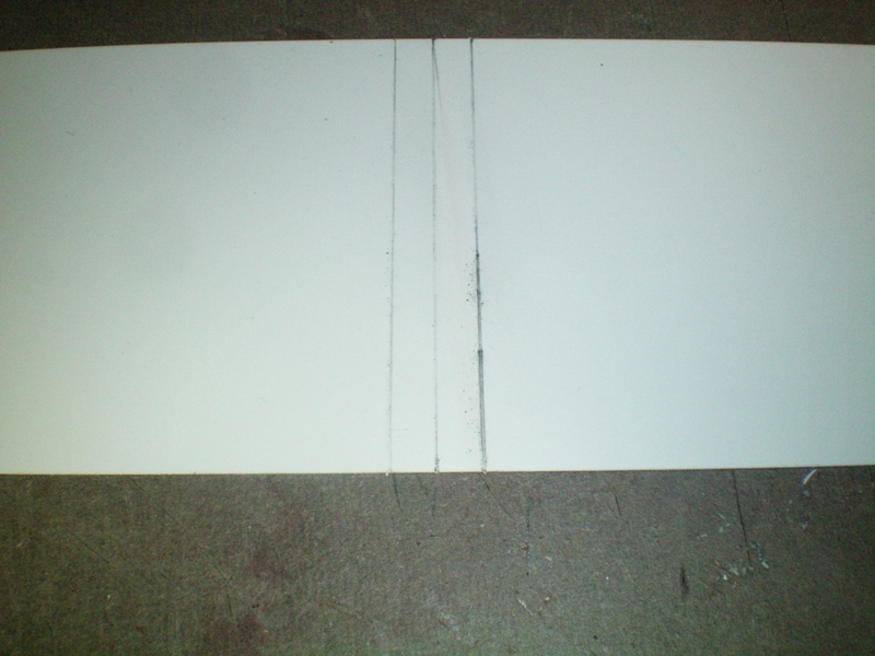 |
Then I scribed a line from the line on the right side of the center line to the corner on the lower right of the sheet. Do the same for the left side.
 |
Here's what it looks like cut. You'll need two of these.
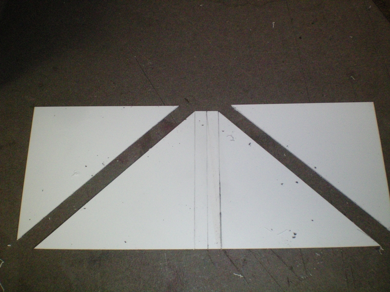 |
Test fitting the two pieces. Looks pretty good.
 |
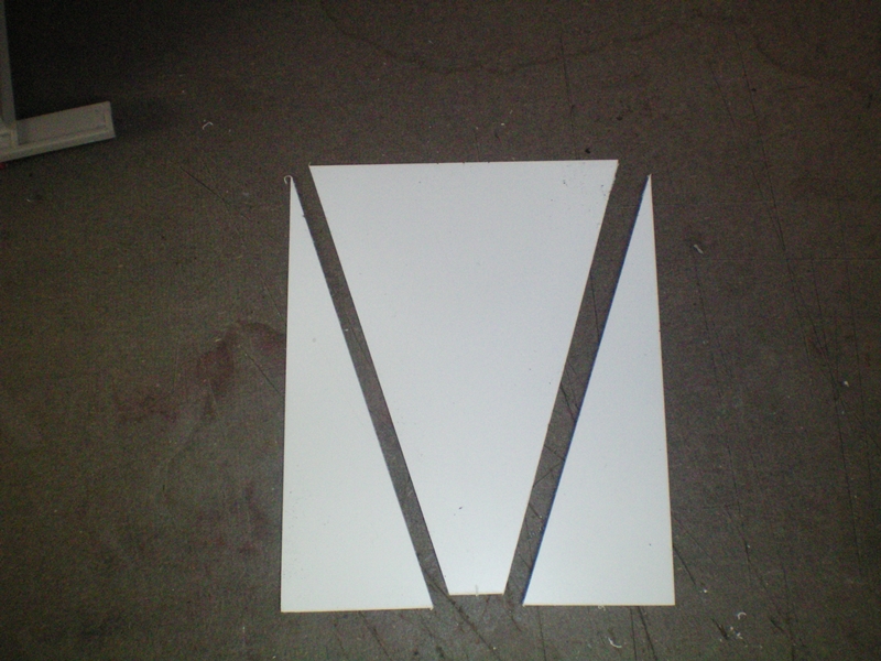
Do the same for the two side pieces. The narrow end should be ½" wide.
 |
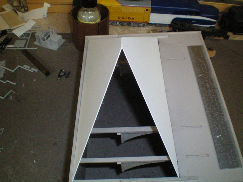
Then start with the larger piece and glue down. Here I'm using a flashlight to help hold the two pieces while the glue dries.
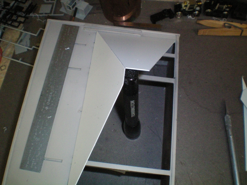 |
This is the way it should look when all the pieces are glued up.
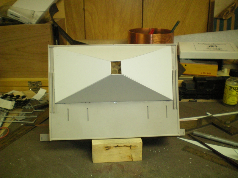 |
And a view down the chute from the top.
 |
Next will be a support structure to hold the whole works while I work on a conveyor system to move the coal from the hopper to what ever it will load.
To be continued