 |
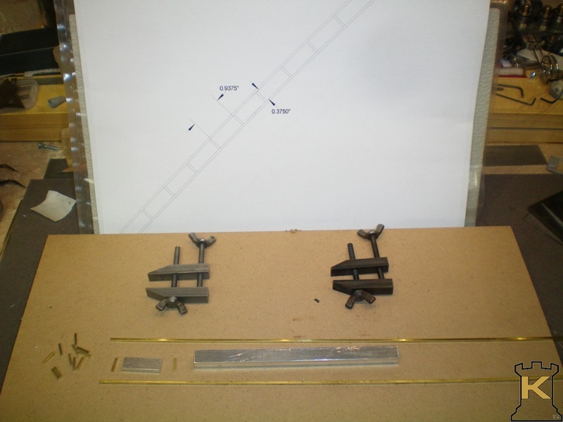
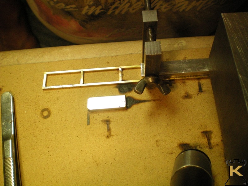
A quick drawing done on Auto Cad, two clamps and a set of aluminum jigs to help align the 3/32" square stock. |
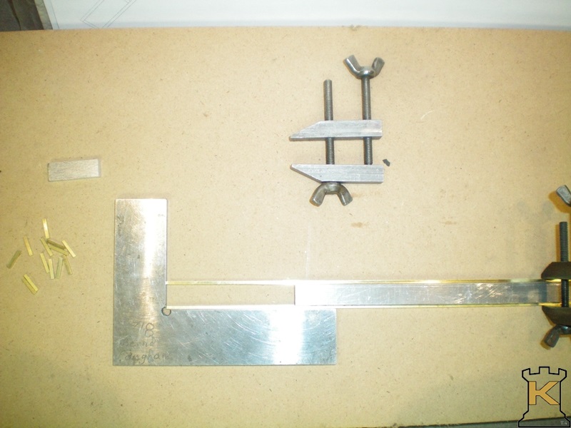 |
Using a square to line up the two ends. Clamp is holding the two pieces of 3/32" stock the correct distance apart. |
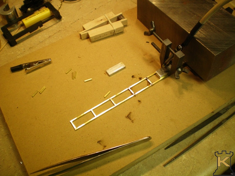 |
Using my home made soldering rig to solder side braces in. |
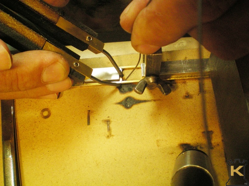 |
Using my home made soldering tweezers worked better. |
 |
The length spacing jig. Corners are a 45° chamfer to clear corner solder joints. |
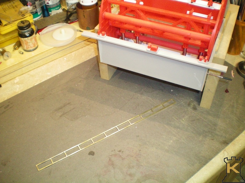 |
One side done almost done. Needs the angle braces yet. |
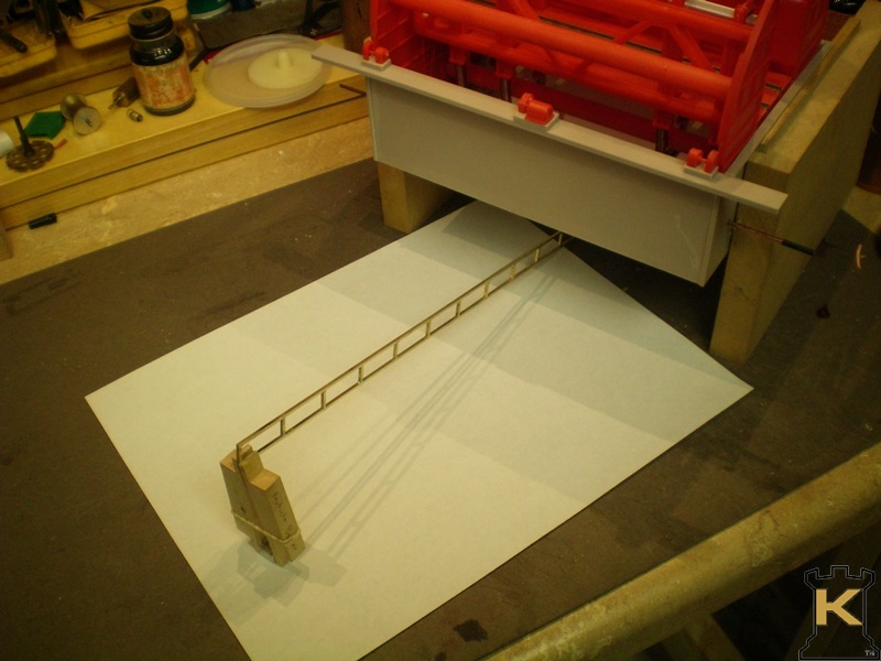 |
This is an approximation of how the conveyor is going to be placed. |
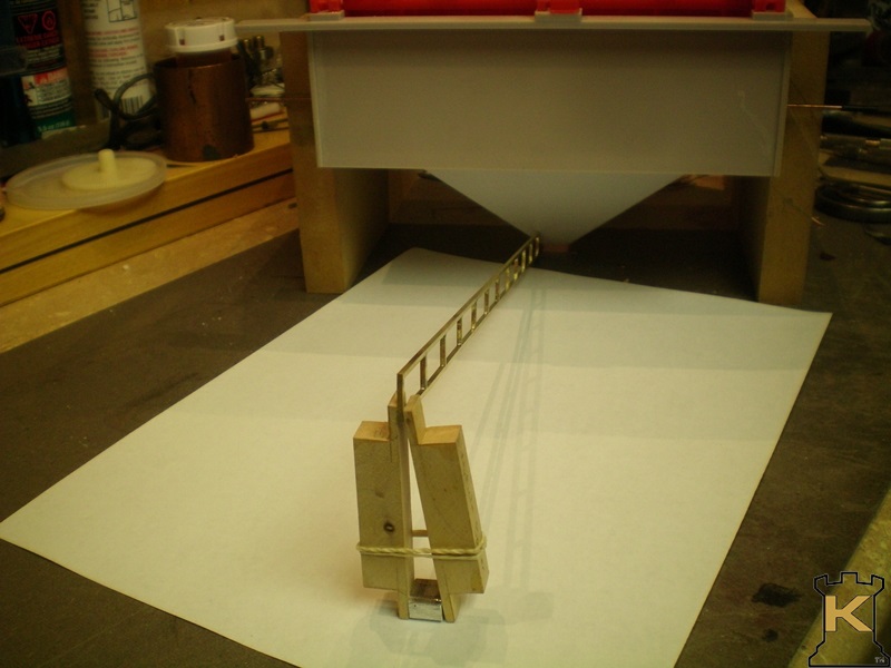 |
In line view of where the end o the conveyor is to be placed. |
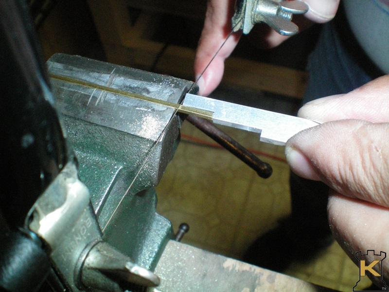 |
Cutting the shorter pieces for the cross members and angle braces. I made a jig to help keep the lengths the same on every piece. |
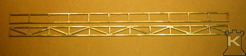 |
One side piece done. The other needs the angle braces installed. |
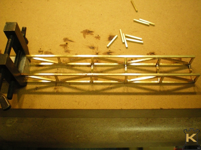 |
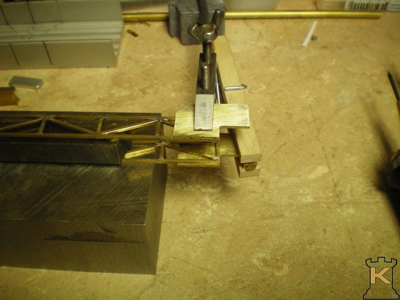
Assembling the two sides with smaller cross members to form the bottom. Another jig was made to hold the sides square and parallel while soldering in the bottom cross members. |
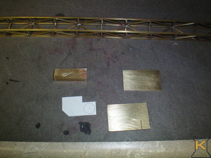 |
Next an end piece where the belt pulley will be mounted is made. Again an Auto Cad drawing helps to make the part. |
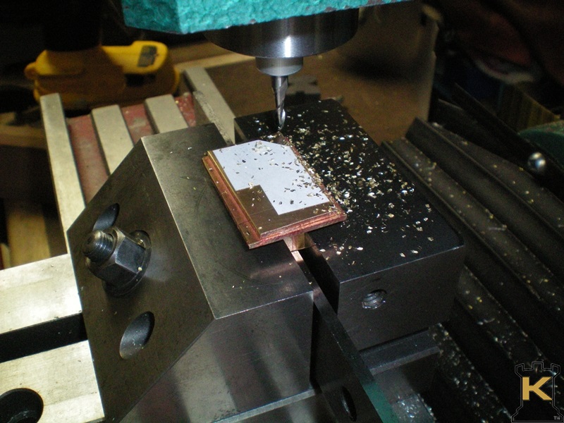 |
Having soldered the two sides together and on a scrap piece that supports the two sides. The part is milled following the drawing lines. |
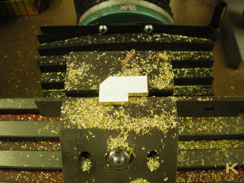 |
The part milled is complete. |
 |
Next the two parts get soldered to the side of the conveyor frame. |
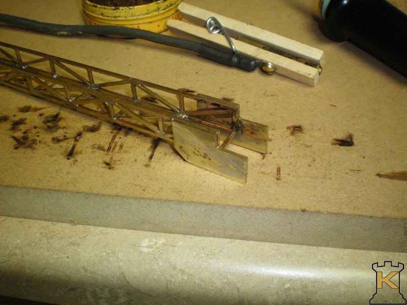 |
Job finished. Now to make a pulley for the belt. |
This is were the project stands at this time. Further progress will be out into the future sometime
since I have another project ahead of this one. Updates will be posted in the "What's New" section on the home page. |